Sunday, February 22, 2009

Fill it up!

Now that the charging is working correctly I was feeling good and decided to finish up the plug. Remember those two circles I cut out for the cooling fans on the controller heat sink? Turns out they are just want I needed. I marked out the three bolt holes. Then I measured the thinner diameter of the plugged and plasma cut that out of the center.


A nice and tight fit. The other side of the plug will come in from the other side and sandwich the plate. I used a 4 prong twist lock 220v 30 amp plug. It's only hooked to the 220 side of the charger. The 110 plug is just laying in the trunk. It won't be used much if at all but is there in case that's all I can get.


A few bolts and the plug was done. Looks pretty cool. When I get time that sticker will be changed or modified just for fun. I think "Premium Electrons Only" will suit this car better now don't you?


Fill it up! Charging will be quick and easy now.

Controller Temperature Sensor

I designed the new computer to monitor the temperature of the motor controller but being in a hurry to drive I didn't make and hookup this sensor until now. After each short drive I keep checking the controller and at least in the winter so far heat is no concern at all. I'm only seeing a few degrees increase in temperature.

Either way it'll be nice to see this temperature while driving so I decided to finish that up.
I used a hobby servo extension cable for the wiring. You can depress the little tabs and remove the connectors from the housing.


Note the position of the wires. It's not the same as the original order on the cable. The LM34 temperature IC from left to right is +, signal, -. Use three small pieces of shrink tubing to protect the terminals and keep them from shorting out on each other.


Next I wrapped all three connection in one larger piece of shrink tubing.


Now to make a housing for this sensor. We want to use something that will conduct and transfer heat quickly so that we can see changes to the temperature quickly. I'm using a small aluminum tubing that I cut a 1" long piece from. The bolt and nut are used to reinforce walls on half of the tube while shaping the other half.


After pounding the unprotected half with a hammer you get a nice flat piece that we can drill into for mounting the sensor somewhere.


A little JB Weld to hold the sensor in place. Shove the sensor to the far end so that it contacts the metal to pick up the heat well although the JB Weld does a fair job at heat transfer from what I've noticed.
Here is the final sensor hooked up and ready to be mounted.

I used a self tapping screw and mounting the sensor on to the heat sink of the controller.


This is temporary as I'm still not sure exactly what I want or need mounted in the car. This little LCD screen is showing the RPM from the computer, the temperature of the motor and the temperature of the controller. The RPM are not needed since the dash has that implemented already. Eventually I'll probably use the microprocessor to determine which of the two is hottest relative to its maximum temperature (which I also am outputting here on the screen for reference) and use the dash temperature gauge to represent that temperature. This way it won't matter which of the two is hot, if you see the gauge getting too high, something is too hot and that's all that matters.
After my first test drive I realized I did something wrong. When driving the temperatures tend to bounce around a little and unless you let off the throttle it's hard to tell the real temp. I didn't run shielded wire from the sensors to the computer. I'll need to pull the front batteries out when I do the AC so I'll rerun those wires at that time.

Friday, February 20, 2009

Charging issues

I made another long trip 26+ miles but it hasn't been all fun. I'm still working on a good cell balancing solution and now I've realized I have some charging issues.

I noticed that when I try to crank up my charging amps (above 6 or 7 amps) the BMS starts freaking out and misreporting cell voltages. Many just go to zero and the BMS triggers for the charger to shutdown.Two things will fix this. First, remove the serial cable from the charger to the BMS. I can turn my amps up to max and the BMS happily reports all cell voltages but of course I now have no protection from over voltage and other alerts. The charger will only charge based off full voltage. The second thing that got it working was completely removing the charger from the trunk and setting it on the garage floor. Now I can leave the serial cable plugged in and it all works fine. Put it all back in the trunk and it's crazytown. It seems I'm getting some kind of EMI going through the serial cable to the BMS which is causing problems but not sure why only in the car.

I didn't notice any of this before because I wanted to start out charging the pack at low levels. I need to be able to charge at much higher rates when making long trips (like going to work) or I might have to sleep over. Oh well all part of being the the few first to do something like this.

UPDATE:
This is now fixed. I had to completely isolate the charger from the car ground. I used some foam stripping that is sticky on one side and placed that between the charger feet and the rack it mounts to. I then placed rubber grommets in the holes on the charger feet so the bolts couldn't touch metal on the charger. Last I used rubber washers between the charger feet and the metal washers. Basically just make sure no metal on the charger touched the car metal. I'm now able to charge at 24 amps!

Monday, February 16, 2009

Inside Drive

I went out for another drive and this time with my neighbor so he could film while driving. The drive was 22.1 miles round trip. The fastest I took the car was ~70 mph but there was more available so we'll have to see what top speed is one of these days. I did a lot of driving at 65-70 when possible and 45-55 when traffic was slow. Overall I consumed a bit over 7000 Wh for an average of 316.74 Wh/mile. I really need to test this while trying to average 55 mph and taking it easy to see what the best is.

Things still look good even driving at these speeds though. My total pack capacity is 23040 Wh. If I try not to go below 80 DOD that gives me 18432 Wh. If we divide that by 7500Wh to play it safe we get 2.4576. Then multiply that by the 22.1 miles we got gives us a range of 54.3 miles driving at 65 in the hills.

My next long test I believe will be out to my Uncle Duane's house. It's about 30-35 miles away and completely flat ground. Maybe 6 to 10 stop signs along the way so I plan to drive it at 55 mph the whole way and see how the efficiency looks.

Friday, February 13, 2009

Three, four and more

The days at work have been long when all you want to do is get home and take the EV out for a spin. A couple days ago I went out and drove the car around a bit to get the pack drained down slightly. When I got it home I reset the watt hours remaining and capacity numbers of the BMS. I charged up and it showed about 6kwh. Last night I then took the car again and sure enough both those numbers drop when driving so this will, for now, be my fuel gauge. Eventually I'll take this data and convert it so that my original fuel gauge works as well but that's low on the priority list right now.

The drive last night was by far the best. I got the front bumper back on and what a difference a little wind resistance makes. I went for a total of 16.2 miles of mixed city and hwy type driving. I got the car to 65 mph and there was plenty of power to spare. One day I'll test out the top speed when I get time and I'm on a nice open stretch.

I was also pretty hard on the throttle last night trying to get a good feel of what the car can do. I ended up using about 6kWh. So if I drive really bad I'm still looking at a 60 mile range. I also calculated 375 Wh/mile. Considering the lead foot this is really good. I'll be trying a conservative drive over the weekend hopefully and try to estimate my best range as well.

Things are really going well! So that was drives three and four. The more is another video of the walk through. Still plan on getting the inside car ride and again hopefully this weekend I can get my neighbor to film that so I can focus on driving.

Have something else you want video of or explained better? Just add a comment and I'll see what I can do.

Tuesday, February 10, 2009

Second drive

Sorry no video or pictures this time but they are coming! I actually had a few errands to run last night when I got home from work so I took the EV out to put some time on the batteries and get those broke in but mostly just to learn more about the nature of the car. I was surprised when I returned home and had put 6.5 miles on just driving around my little town.

I'm learning the torque curves a lot better now and this thing can really accelerate if you shift right. I'm becoming more impressed with the performance as the driver gets better.

I was having trouble figuring out the remaining capacity on the BMS system and after talking with Elite it turns out I need to do some rewiring. Apparently this system also tracks the current being charged into the cells and my wiring design didn't take this into account so add that to the list of remaining items.

Still to do:
- Put my front bumper back on.

- Finish wiring the BMS system inside the car. It's just sitting there on the console and needs to be mounted. Turns out there is also no way to turn the power off to the BMS computer or the BMS monitor so I will be installing two switches. The monitor only needs to be on if you want to see the output (driving). The computer needs to be on while driving or charging but you could turn it off otherwise.

- Build covers for the cells so they are not completely exposed and a potential hazard.

- Finish the electronics and wiring for the heater.

- Setup DC/DC converter to switch on only when ignition is on.

- Fabricate the serpentine pulley for the AC and get that all mounted up.

- Add a protective shroud under the motor. It's a pretty clear shot between it and the ground right now so preventing anything from bouncing / spraying directly onto or into the motor would be a good idea.

- DMV registration

Probably some other little details I'm forgetting but that's the schedule for the time being.

I'll be trying to do a video with a quick walk through of the car and components with an inside drive this weekend if time permits.

Monday, February 9, 2009

First Test Drive

It's been a long and painful wait getting to the point for the first test drive of my car but the wait is over! This weekend I was able to get the car to the point I could go for the first test drive and I'm still grinning. The video isn't the greatest since it was getting dark. I'll be adding another video in better lighting which also shows under the hood and trunk along with an inside the car test drive later this week.

Sunday, February 8, 2009

Wiring it all up.

I've actually been a little behind on the blog. Being so close to the point of a test drive I was putting all my time into the build. Sadly I even forgot to take pictures of all the things I had planned but there are still some good shots.


It's time to wire everything up. To do this you need some form of conduit from the front to the rear of the car in almost all EV builds since usually batteries and components are not all in one location. I used what is known as Smurf tubing because of the Smurf blue color. It's just a 3/4" plastic flex tubing designed high voltage applications in homes. It's light weight, again flexible, and reasonably priced. I think I paid $30 for 100 ft at Home Depot. I also picked up some orange flex for the low voltage wiring. It's technically the same tubing from what I can tell but the color coding is standard (low voltage = orange, high voltage = blue).


In order to connect the rear cells to the BMS system I needed to run 28 wires from the front to the rear of the car. This is to support two BMS voltage modules (11 wires each for cell voltage and 3 for temperature). In addition I ran a 10 gauge solid strand back as well. This gives me a positive 12v line from the DC/DC converter I'll be putting in the trunk to charge the original 12v battery. The DC/DC converter takes the traction pack which in this case is 144v nominal and charges my 12v system essesntially replacing my alternator.


Here is that low voltage run.


Another shot of the uncut wires hanging out of the trunk area.


I installed two runs of the high voltage tubing. Because of the size of the 2/0 traction wiring I could only fit one cable per tubing. I additionlly pulled an 8 guage solid strand wire from the most postive terminal on the front battery pack to connect to the charger. The most negative terminal of the traction pack will be in the rear of the car already so we can attach directly to that terminal later.


The installation of the two other tubings was nothing special but thought I'd show how I closed up the tubing. There are connectors you can get for the tubing to run it into junction boxes etc. These at least reduced the opening diamter some. After crimping on the terminal I added a layer of wire loom to protect the exposed portion of the wire.


Next I wrapped the whole thing with electric tape and finished it off by heat shrinking the ends.


Here is a shot of the three flex tubings coming into the trunk secured by some jumbo sized zip ties. You can also see the DC/DC converter setting in place on the right.


Here is the installed DC/DC converter. I see a lot of people installing this up front in the car. The thing that bothered me was you can easily see in to the electronics of this thing. Maybe it's moisture resistent but I didn't want to take any chances so I decided to place it in the trunk. It made for some extra work but I feel better about having it here where I know things stay dry. These converters actually come with your standard 110v AC outlet cord attached which may scare some. Internally this AC voltage is converted to DC using some sort of bridge rectifier. When sending it direct DC only half of the rectifier is working but the end result is the same. You can simply cut off the 110v plug and wire it to your traction pack. It doesn't matter which wire is positive and which is negative. Next to the big black high voltage power wire you can see the two smaller 12v output wires. The black wire is ground and runs just to the right where there was a convenient bolt to ground to. The white wire as I mentioned before is ran into the low voltage conduit to the front of the car.


Here is the 12v + wire coming from the DC/DC converter and guess where I connected it. That's right the original location the alternator use to be connected. This is the small circuit panel under the hood on the driver side of the car.


Here is the high voltage wiring. This isn't as neat as I hoped for but I was really running out of room and had to place these components close together. The two outside, funny, shiney looking things are the contactors. These are basically giant SPST relays that are designed to handle high voltage and high current. I went with two just for the added fail safe. One contactor closes when the igntition is turned on. The second closes as you depress the accelerator. Additionally there is another low current relay which you can barely see right in the middle of it all which tells the controller when it's ok to run. I plan to add an array of safety features later that will turn one or more of these relays off until all the safety requirements are met. These can be things like the car isn't still plugged in to the wall outlet to controlling the RPM limit of the motor. Towards the bottom is the KLK fuse (white round thing). This is rated for 250 volts and 500 Amps. You'll want to use one of these for every group of battery packs you have. This way if a short happens the fuse will blow and you won't loose your batteries. Last on the bottom left is the giant anderson connector. You can disconnect this to guarantee all high voltage is removed from the system. BEWARE, however, the capacitors in the controller will continue to carry a charge after disconnected.


This is a picture on the other side of the controller. The big black box with the 2/0 cable running through the sensor that detects how much current is being used when driving. This is like a MPG gauge and helps you judge how efficiently you're driving. On the far left is the pot box. This is 5k variable resistor which you connect your original throttle cable to. Now the further you press on the original accelerator the faster you go, just like a gas car. The last thing here is a small fuse block. I tapped into the 12v ignition line from under the dash and ran a line up to the front. When you turn on the ignition now it triggers a relay which then supplies voltage to this fuse block. From here I'm running the vacuum pump and the 12v fan that cools the controller.


Here is a final shot of everything wired up and ready to go.


Now it's time to charge it up and have a test drive!

Friday, February 6, 2009

The controller

With the batteries in I knew how much room I had left to work with up front. It was time to build the control board. This board will be nice surface to mount many of the high voltage components to. I ended up using polypropylene (I think 3/8" thick). It's a little more expensive than using some type of wood but is still easy to work with and doesn't have to be sealed and painted later to make it last.

Next I have to wonder how I let so many weeds crop up in my yard. Right! I have done nothing but work on this car for several months. Below I'm setting up a straight guide for cutting the material. I made the mistake of using a metal bit in the jigsaw and ended up with goo. The blade got too hot and polypropylene started melting. You can probably stick with the jigsaw and a wood bit but I didn't confirm that. I ended up switch to the Sawzall with a wood blade. This blade has massively aggressive teeth and was able to cut the material quickly without causing any heat and made for a clean cut. However you cut it, the trick is to do it fast before it gets hot.


I found this heat sink on eBay for $20. What a deal. It wasn't the exact size I needed but very close. You can buy a ready to go heat sink from Curtis but it's like $300+ or something crazy. EV America sent me a flat piece of aluminum for a heat sink which they claim works just fine but I wanted to overdue the cooling on this component since I had the option. I needed to trim off a few of the fins and drill some holes to match the holes already on the controller for a heat sink.


I ended up using the small sheet of aluminum they gave me anyways to provide a mounting surface on the top side of the board. Without this the controller would just fall through since the a hole needed to be cut that was large enough to let the heat sink pass through. You can also see a very thin piece of sheet metal I used to attach the fan(s) too. I current only am using one fan but installed the option for fan two in case I needed to add a second one later.


Did a quick test fit to make sure it all works together nicely before applying the heat compound.


This was like being in kindergarten again. Finger painting is great! I'm applying the heat compound. It needs to go on all pieces of connecting metal. In this case that was actually four sides of metal: The Controller, the metal support plate (both sides), and the heat sink itself.


I started loosely laying components on the board to get an idea of where things might fit. It's gonna be tight.


Finally the control board all installed.

Next we need to wire everything up.

Wednesday, February 4, 2009

Rear batteries installed

OK I've finally got the rear batteries installed. I had to rebuilt this rack a second time or I would have posted this during the front battery install post. I also seem to have lost the picture of the rack by itself so you can really see the mounting points but there are four feet that come off from the sides and I used 5/16" grade 8 bolts to secure it to the trunk. Be careful that the holes are far enough out. I noticed that there are two layers to the metal work here and if you drill just past the sides of the trunk where it dips down you'll enter a cavity that you can't actually get to from the bottom and therefore can't attach the nuts to the bolts. You could use a lag bolt but that has a good chance of just ripped out with the thin metal here. Speaking of, use a nice wide washer on both sides to get a lot of surface area.

Here is the first picture that wasn't lost after the batteries are mounted.


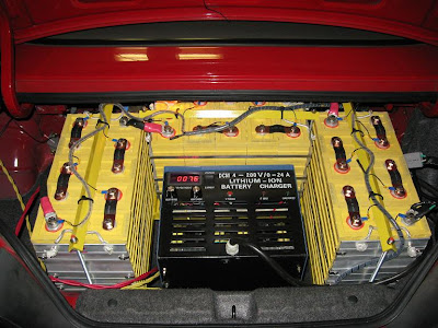
Here is a top down view to show the room left over. Ah some storage space you say still....I wish. I've decided to, at least for now, use the jumbo charger inside the car. I'll probably replace it someday with something smaller and gain some room back....we'll see. If you look at the bottom of the picture you'll see some large metal feet that I've added. The charger will bolt to these.


Here is the charger in place with the BMS wiring all attached. This is kind of a fast forward in time shot really since if you look closely you'll notice I'm already charging as well. You can also see some unprotected yellow and red wires in the left side of the picture. These are the two sets of power wires for the charger (110v, and 220v). I haven't finished installing the final plugs for these so that still needs to be done.